


Intersections
'Intersections' pertains to multiple design elements concerning intersections, including: alignment, channelization, grades, off set, radii, sight distance, signalization, spacing, and traffic control devices:
Alignment
(Angle of intersection)
A measure of the horizontal alignment where two or more roadways join or cross, measured at the intersecting centerlines.
Standards
AASHTO & PennDOT: As close to 90° as possible, but a minimum of 60°.
Comments
Since intersections represent points of conflict and are potentially hazardous, the alignment should provide adequate sight distance and allow users to maneuver safely with minimum interference. Roads intersecting at acute angles require extensive turning roadway areas and tend to limit visibility, particularly for truck drivers. When a truck turns on an obtuse angle, the driver has blind areas on the right of the vehicle. Acute-angle intersections increase the exposure time of the vehicles crossing the main traffic flow and may increase the accident potential.
According to PennDOT, realigning roadways that intersect at acute angles may prove beneficial. But angles above 60° do not warrant realignment closer to 90° since it produces a small increase in visibility.
Recommendation
As close to 90° as possible, but a minimum of 60°.
Intersection Alignment
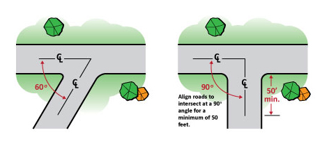
Align roads to intersect at a 90 degree angle for a minimum of 50 feet.
Channelization
(Islands or pavement markings)
The islands or pavement markings that delineate the travel lanes and turning lanes.
Standards
Manual on Uniform Traffic Control Devices (MUTCD)
Comments
Channelized islands should be placed so that the proper course of travel is immediately obvious, easy to follow, and of unquestionable continuity. Properly placed islands are advantageous where through and turning movements are heavy. The use of curbed islands generally should be reserved for multi-lane highways or streets and for more important intersections on two-lane highways. In or near urban areas where speeds are low and drivers are accustomed to confined facilities, channelization can be expected to work well.
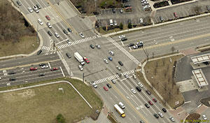
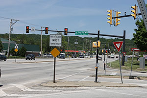
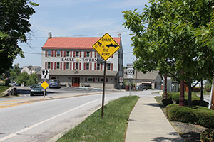
Aerial image of the US Business 30 and PA 100
intersection in West Whiteland Township, PA.
Painted or striped channelization can be made to increase efficiency and safety and has the advantage of easy modification when warranted by driver behavior (ITE). This type of channelization may be used initially to establish the best layout arrangement before the permanent construction of islands, if necessary.
Islands serve several purposes including:
- separation of conflicts;
- control of angle of conflict;
- reduction in excessive pavement areas;
- regulation of traffic and indication of proper use of intersection;
- arrangements to favor a predominant turning movement;
- protection of pedestrians;
- protection and storage of turning and crossing vehicles; and,
- location of traffic control devices.
Recommendation
Follow the guidelines of the Federal Highway Administration's, Manual on Uniform Traffic Control Devices (MUTCD).
Grades
(Vertical alignment or profile)
The rise and fall of a given roadway at an intersection.
Standards
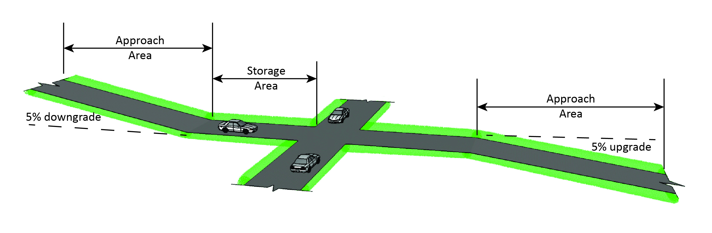
AASHTO: Grades in excess of 3 percent should be avoided. Where conditions make designs unduly expensive, grades should not exceed 6 percent. Storage areas should be flat or 0.5 percent minimum to 2 percent maximum.
Comments
Intersecting roads should permit users to discern and easily perform the maneuvers necessary to pass through the intersection safely and with minimum interference from other users. A level, storage area prior to the intersection improves the operational capabilities and safety characteristics of an intersection.
Recommendation
Recommend use of AASHTO standards.
Intersection Grades
Radii
(Turning radius, turning path or curb radii)
A measure of the sharpness of the corner formed by two intersecting streets, independent of the angle at which the streets intersect.
Standards
AASHTO:
Rural
- 50 foot minimum
- 35 foot minimum on local roads with low truck volumes
Urban
- 15 foot minimum, 25 foot desirable on local roads with pedestrians
- 30 foot minimum for industrail areas and arewas with higher truck volume
PennDOT
Recommended use of AASHTO standards with these additions:
- 25 foot minimum for minor cross streets
- 30 foot minimum for major cross streets
- 40 foot minimum with high truck volumes
Comments
Intersections should be designed to accommodate the expected amount and type of traffic and allow for safe turning speeds. Intersections designed with a corner radius to accommodate the largest vehicles anticipated, eliminate the problem of increased traffic conflict and vehicles driving over the curb.
Turning radii should reflect the presence of transit bus routes. It is recommended that minor allowances be made to the standard turning templates to address varying driving conditions and situations. Stop bars at controlled intersections should be placed so that the transit vehicle avoids crossing the center line of the roadway to make turns. The placement of traffic signal loop detectors may also be affected by the need to address buses making turns.
There must be a balance in determining curb radii for collector and local streets. Caution should be taken not to over or under design the radius. As the curb radius increases, the paving cost and intersection area required for pedestrian movement also increase, dangerous "rolling stops" become more frequent, and higher turning speeds are encouraged. (ULI)
Recommendations
- Recommend use of PennDOT standards for state highways.
- Recommend 5-15 foot minimum on local roads.
Sight Distance
(Corner sight distance)
The maximum distance that a driver can see objects such as traffic signs, pavement markings and moving objects. Corner sight distance is measured from a point fifteen feet from the edge of the major roadway and measured at eye height, 3.50 feet, to an object 3.50 feet above the pavement.
Standards
AASHTO:
Minimum Corner Intersection Sight Distance (Feet)
| 2-Lane Roadway* | 4-Lane Roadway* | ||||
|---|---|---|---|---|---|
| Design Speed (MPH) | Local/Collector | Arterial | Local/Collector | Arterial | |
| 60 | 650** | 1050** | 710** | 1170** | |
| 50 | 515 | 875 | 580 | 975 | |
| Rural and Suburban |
40 | 415 | 700 | 475 | 790 |
| 30 | 310 | 530 | 350 | 590 | |
| 20 | 210 | n/a | 240 | n/a | |
| Urban | 200 foot minimum, 300 foot desirable | ||||
*The number of lanes and highway functional classification refers to the highway being intersected. **At 60 MPH, stopping sight distance governs.
The primary purpose of establishing a clear sight triangle is where no traffic control device exists or where a yield sign is used. The practice of providing a clear area free of obstructions is still a good practice but it should be used in conjunction with adequate intersection sight distances.
Comments
Each intersection contains several potential vehicle conflicts, the possibility of these conflicts actually occurring can be greatly reduced through the provision of proper sight distances and appropriate traffic controls.
The operator of a vehicle approaching an intersection at-grade should have an unobstructed view of the entire intersection and sufficient length of highway to permit control of the vehicle to avoid collisions. The sight distance considered safe under various assumptions of physical conditions and driver behavior is directly related to vehicle speeds and to the resultant distances traversed during perception and reaction time and braking.
The object being viewed should be measured at a height of 3.5 feet. The reason for this is that the first part of an approaching vehicle that is observed is approximately 3.5 feet high.
Recommendations
- Follow the recommendations of PennDOT's Publication 70M, Guidelines for the Design of Local Roads and Streets for intersection sight distances. Use rural and suburban classifications for townships and use the urban classification for boroughs and cities.
- Provide a clear area or, clear sight triangle, free of obstructions in conjunction with adequate intersection sight distances.
Intersection Sight Distance

Intersection Sight Triangle
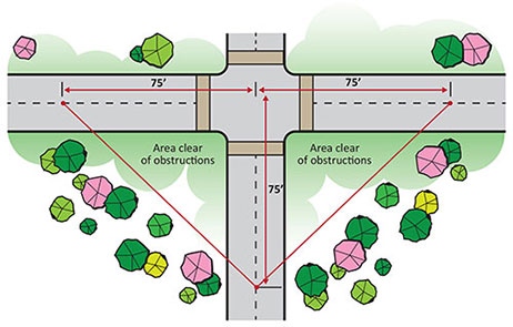
Clear sight triangle is not synonymous with intersection sight distance. There is a distinct difference between the two as illustrated above. Most municipalities use a clear sight triangle of 75 feet. A clear sight triangle improves the sight distance for the approach to the intersection but the more critical value is the sight distance at the stopped position.
Signalization
(Traffic control signals)
Any power-operated traffic control device, other than a barricade warning light or steady burning electric lamp, by which traffic is warned or directed to take some specific action.
Standards
PennDOT: Recommended use of the MUTCD; the Pennsylvania Code, Title 67, Chapter 212, Official Traffic Control Devices for signal warrants; PennDOT Publication 149 Traffic Signal Design Handbook; PennDOT Publication 408 Specifications; and the PennDOT Publication 148 Traffic Standard Drawings, TC-7800 Series.
The system for establishing the need for signal installation is known as "signal warrants". There are twelve warrants for traffic signals. Presented as an example, Warrant 1, Minimum Vehicular Volume, is intended for application where the volume of intersecting traffic is the principal reason for consideration of signal installation. These warrants should be thought of as a guide rather than absolute criteria.
Minimum Vehicular Volumes for Signal Warrant One
| Number of Lanes for Moving Traffic on Each Approach | Vehicles per Hour on Major Street (Both Approaches) | Vehicles per Hour on Higher Volume Minor Street Approach (one direction only) | |
|---|---|---|---|
| Major Street | Minor Street | ||
| 1 | 1 | 500 | 150 |
| 2 or more | 1 | 600 | 150 |
| 2 or more | 2 or more | 600 | 200 |
| 2 or more | 2 or more | 500 | 200 |
Comments
Contrary to common belief, traffic signals do not always increase safety and reduce delay. Experience has indicated that, although the installation of signals may result in a decrease in the number and severity of right-angle collisions, signals will, in many instances, result in an increase in rear-end collisions. Further, the installation of signals may not only increase overall delay but may also reduce intersection capacity.
Recommendations
Follow the recommendations of the: MUTCD; the Pennsylvania Code, Title 67, Chapter 212, Official Traffic Control Devices for signal warrants; PennDOT Publication 149 Traffic Signal Design Handbook; PennDOT Publication 408 Specifications; and the PennDOT Publication 148 Traffic Standard Drawings, TC-7800 Series.
Spacing
(Distance between intersections)
The minimum spacing between intersections measured from centerline to centerline.
Standards
AASHTO A Policy on Geometric Design of Highways and Streets
Comments
The functional deterioration of arterials and collectors is a result of the proliferation of inadequate access management that generates operational and accident problems. The greater the number of access points per mile the greater the accident rate. When adjacent intersections and driveways are situated close together, the overlapping maneuver areas conflict and reduce total capacity. (ITE)
The location and spacing of intersections and driveways should be based on the following factors:
- functional classification;
- design speed and grade of the highway;
- signal spacing;
- number, volume and location of existing access points;
- lot width; and,
- sight considerations.
Recommendations
Based upon a review of the recommendations of various sources, the following charts are suggested as a reference in determining intersection spacing. This process is complex and may be interpreted as an oversimplification and should therefore only be used as a guide. The values provided in these charts are interpolated based on the fundamental points of:
- signal spacing (1-4 per mile),
- corner clearance,
- intersection off-sets,
- driveway spacing; and,
- number of driveways per half mile.
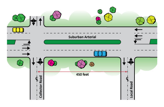
The charts only identify suburban and rural roads because most urban roads are already developed. To use the chart, establish whether the area is suburban or rural, then determine the function of the primary road. The next step is to determine the function of the two intersecting roadways. For example: if the primary road is a suburban arterial and the two intersecting roadways are a collector and a local road the suggested distance between these two intersections is 450 feet from centerline to centerline.
Suburban Arterial (feet)
| Arterial | Collector | Local | Driveway | |
|---|---|---|---|---|
| Arterial | 2640 | 2000 | 500 | 230 |
| Collector | 2000 | 1500 | 450 | 175 |
| Local | 500 | 450 | 400 | 100 |
| Driveway | 230 | 175 | 100 | A |
Rural Arterial (feet)
| Arterial | Collector | Local | Driveway | |
|---|---|---|---|---|
| Arterial | 5280 | 2640 | 500 | 230 |
| Collector | 2640 | 2000 | 450 | 175 |
| Local | 500 | 450 | 400 | 100 |
| Driveway | 230 | 175 | 100 | B |
A - For access management purposes, permit no more than 10 access points per half mile.
B - For access management purposes, permit no more than 9 access points per half mile.
Suburban Collector (feet)
| Arterial | Collector | Local | Driveway | |
|---|---|---|---|---|
| Arterial | 2640 | 1500 | 500 | 115 |
| Collector | 1500 | 1000 | 450 | 85 |
| Local | 500 | 450 | 400 | 50 |
| Driveway | 115 | 85 | 50 | C |
Rural Collector (feet)
| Arterial | Collector | Local | Driveway | |
|---|---|---|---|---|
| Arterial | 2640 | 2000 | 500 | 115 |
| Collector | 2000 | 1500 | 450 | 85 |
| Local | 500 | 450 | 400 | 50 |
| Driveway | 115 | 85 | 50 | D |
C- For access management purposes, permit no more than 12 access points per half mile.
D - For access management purposes, permit no more than 14 access points per half mile.
Intersection Spacing
Traffic Control Devices
(Traffic control signals or signs)
Any sign, signal, marking or device placed or erected for the purpose of regulating, warning or guiding vehicular traffic or pedestrians, or both.
Standards
PennDOT: Recommended use of the MUTCD; the Pennsylvania Code, Title 67, Chapter 212, Official Traffic Control Devices for signal warrants; PennDOT Publication 149 Traffic Signal Design Handbook; PennDOT Publication 408 Specifications; and the PennDOT Publication 148 Traffic Standard Drawings, TC-7800 Series.
Comments
Signing and marking are directly related to the design of the highway or street and are features of traffic control and operation that the designer must consider in the geometric layout of a facility. The signing and marking should be designed concurrently with the geometrics since future operational problems can be reduced significantly if both are treated as an integral part of design.
Although safety and efficiency of operation depend to a considerable degree on the geometric design of the facility, the physical layout must also be supplemented by effective signing as a means of informing, warning and controlling drivers. Signing plans coordinated with horizontal and vertical alignment, sight distance obstructions , operation speeds and maneuvers and other applicable items should be worked out before design completion. (PennDOT)
Recommendations
Follow the recommendations of the: MUTCD; the Pennsylvania Code, Title 67, Chapter 212, Official Traffic Control Devices for signal warrants; PennDOT Publication 149 Traffic Signal Design Handbook; PennDOT Publication 408 Specifications; and the PennDOT Publication 148 Traffic Standard Drawings, TC-7800 Series.
Traffic signals; Traffic signs.